


Defeating Glass-Fiber Wear: Steel Selection Matrix for 1M+ Shot Tooling
An Engineering Guide to Tool Steel Selection, Vacuum Heat Treatment, and SPI Class 101 Architecture for 30% Glass-Filled PBT
Executive Summary & Bottom Line Up Front (BLUF)
Direct Answer to the Engineer’s Query:
When specifying an injection mold for 1,000,000+ cycles (SPI Class 101) running 30% glass-filled polybutylene terephthalate (PBT-GF30), none of S136, H13, or DC53 alone is an optimal monolithic cavity material.
- S136 (AISI 420 ESR, 48–52 HRC): Excellent chemical corrosion resistance against flame-retardant PBT outgassing, but suffers severe abrasive gate wash-out and runner erosion before reaching 600,000 shots due to hardness capped at ~52 HRC.
- H13 (AISI H13 ESR, 46–50 HRC): Superior thermal shock resistance and toughness, but lacks sufficient abrasive wear resistance and is highly vulnerable to corrosive halogen/acidic attack from degraded PBT flame retardants.
- DC53 (Cold-Work Die Steel, 60–62 HRC): Outstanding abrasion resistance and compressive strength, but vulnerable to chemical pitting (only 8% Cr), lower bulk toughness in thin rib sections, and high risk of brittle cracking under hydraulic shock.
The Kenvox Engineering Standard: The proven, high-reliability solution is a Modular Hybrid Tooling Architecture:
- Primary Cavity/Core Inserts: S136 Premium ESR vacuum hardened and triple-tempered to 50–52 HRC to resist corrosive outgassing and stress-corrosion cracking.
- High-Velocity Impingement Zones (Gates, Sub-Inserts, Deflector Pins): DC53 (60–62 HRC) or Powder Metallurgy Steel (Uddeholm ELMAX or Böhler M390, 58–60 HRC) equipped with Physical Vapor Deposition (PVD) CrN or TiAlN coating (3,000+ HV).
1. The Tribological & Chemical Challenge: 30% Glass-Filled PBT
Engineering resins with high inorganic fiber loading present a compound degradation mechanism that destroys standard production tooling:
                      Compound Tool Wear Mechanism in PBT-GF30

   [ Mechanical Abrasion ]                        [ Chemical Corrosion ]
   • E-Glass fibers (Mohs 6.0–6.5)                 • Brominated/Phosphorus flame retardants
   • Injection pressure: 90–140 MPa                • Thermal degradation volatiles (HBr, acids)
   • Shear velocity at gate: >10 m/s               • Cavity temperature: 80°C–120°C
              │                                               │
              └───────────────────────┬───────────────────────┘
                                      ▼
                        Synergistic Tool Destruction:
               Micro-grooving + Pitting + Micro-fatigue Spalling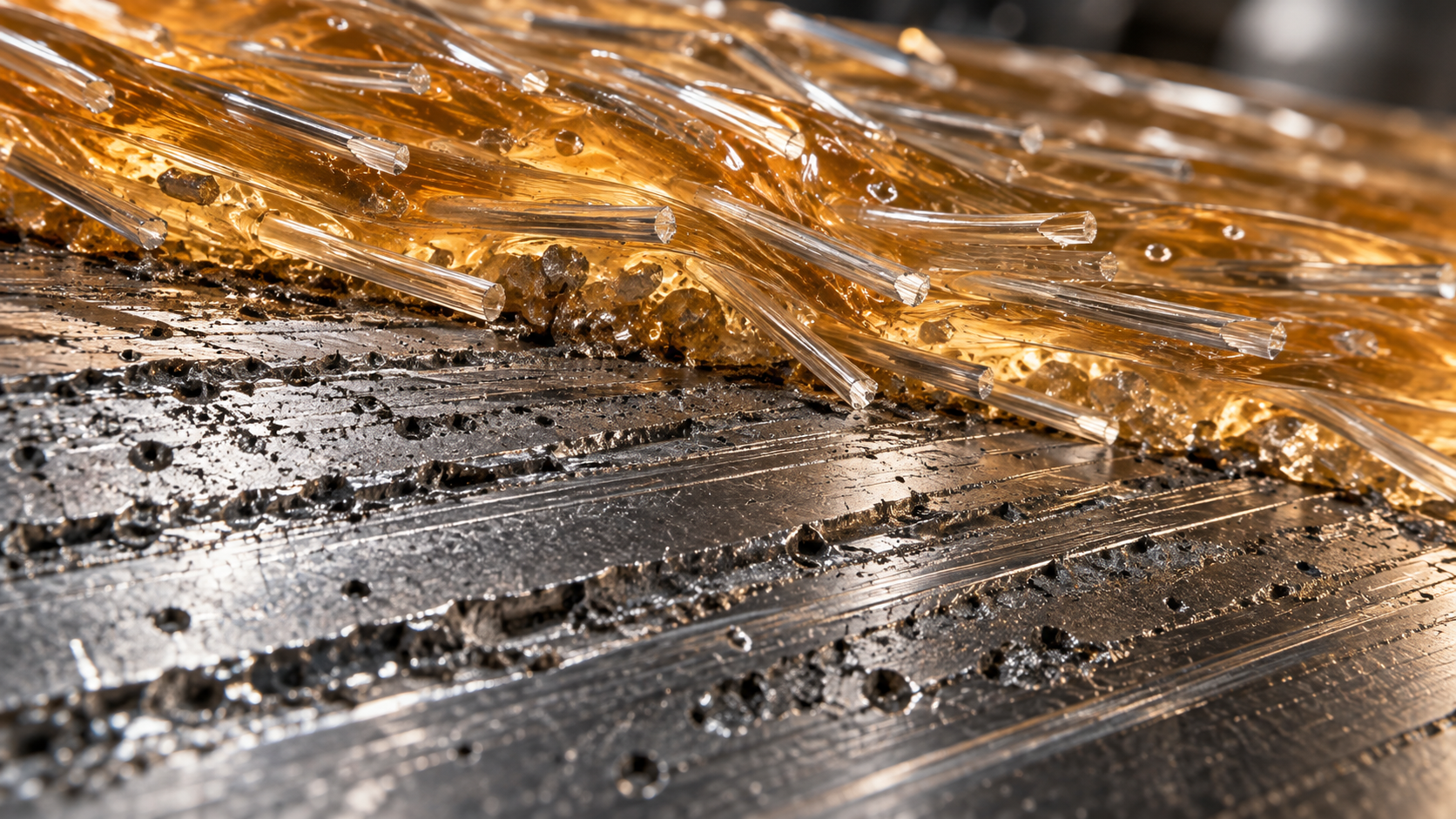
- Abrasive Wear (Two-Body & Three-Body):
E-glass fibers have a Mohs hardness of 6.0 to 6.5 (~600–700 HV), exceeding the hardness of standard pre-hardened steels (P20/718H at 30–34 HRC / ~300–330 HV) and matching hardened tool steels (~50 HRC / ~520 HV). Under 80–130 MPa injection pressure and gate velocities exceeding 10 m/s, exposed fibers cut micro-channels along runner paths, sub-gates, and core pin faces. - Chemical & Acidic Corrosion:
Flame-retardant PBT grades (UL94 V-0) release halogenated compounds (e.g., brominated oligomers) and acidic degradation products when subjected to shear heating (>260°C). These acidic volatiles condense on venting channels, parting lines, and EDM-textured cavity faces, initiating galvanic micro-pitting that accelerates abrasive spalling. - Compressive Fatigue & Parting Line Collapse:
Over 1,000,000 clamp-and-injection cycles, low-yield-strength steels deform at kiss-off surfaces and thin parting shutoffs, creating flash that escalates mold maintenance downtime.
2. Steel Selection Comparison Matrix (SPI Class 101 Standard)
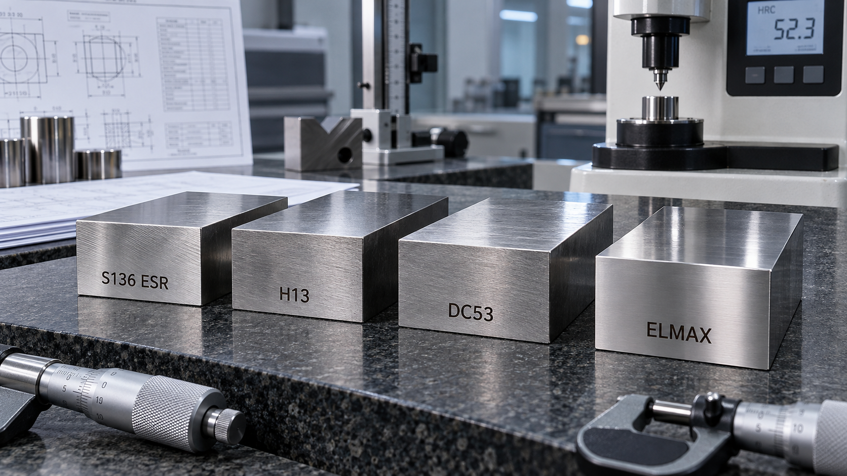
The table below contrasts the mechanical, tribological, and chemical properties of S136, H13, DC53, and Powder Metallurgy (PM) steels for 1,000,000-shot PBT-GF30 tooling.
| Engineering Metric | S136 ESR (AISI 420 Mod) | H13 ESR (AISI H13) | DC53 (Cold-Work Mod D2) | Premium PM (ELMAX / M390) |
|---|---|---|---|---|
| Material Category | Martensitic Stainless | Hot-Work Tool Steel | High-Toughness Cold-Work | Powder Metallurgy Stainless |
| Standard Heat Treat Hardness | 48 – 52 HRC | 46 – 50 HRC | 60 – 62 HRC | 58 – 60 HRC |
| Chromium (Cr) Content (%) | 13.6% | 5.2% | 8.0% | 18.0% – 20.0% |
| Abrasive Wear Resistance | Moderate (Index: 3.5/10) | Low-Moderate (3.0/10) | Extreme (8.5/10) | Superior (9.5/10) |
| Corrosion Resistance | High (8.5/10) | Low (2.0/10) | Low-Medium (4.0/10) | Maximum (9.5/10) |
| Core Toughness (Charpy V-Notch) | 18 – 22 J/cm² | 25 – 30 J/cm² | 12 – 16 J/cm² | 20 – 24 J/cm² |
| EDM Micro-Cracking Sensitivity | Moderate | Low | Moderate-High | Low |
| Polishability (SPI A1/A2 Spec) | Excellent (Mirror A1) | Good (A2/A3) | Moderate (B1/B2) | Superior (A1+ Micro-Clean) |
| Expected Mold Life (30% GF-PBT) | 400,000 – 600,000 shots | 300,000 – 450,000 shots | 800,000+ (Dry/Non-FR) | 1,500,000+ shots |
| Failure Mode in PBT-GF30 | Gate washout, edge rounding | Pitting rust & abrasive wear | Acid pitting, micro-chipping | Uniform sub-micron abrasive wear |
| Primary Optimal Role | Cavity/Core Base Inserts | Mold Bases / Structural Blocks | Replaceable Gate / Core Pins | Critical Optical / Micro-Tolerance Inserts |
3. In-Depth Steel Metallurgy & Failure Analysis
3.1 S136 ESR (AISI 420 ESR Stainless)
- Metallurgical Profile: S136 is an Electro-Slag Remelted (ESR) martensitic stainless steel with ~0.38% Carbon and 13.6% Chromium.
- Why Designers Select It: Outstanding atmospheric and chemical corrosion resistance, minimal oxidation during water jacket cooling, and exceptional mirror polishability (SPI A1 finish).
- The Failure Mode at 1M Shots: S136 is carbide-lean. With maximum through-hardness limited to 50–52 HRC, the matrix cannot withstand the cutting action of fragmented glass fibers at narrow gates. By shot 500,000, tunnel gates and edge gates exhibit 0.05–0.12 mm dimensional enlargement ("gate blowout"), causing pressure drops, flash, and part weight variance.
3.2 H13 ESR (AISI H13 Hot-Work Steel)
- Metallurgical Profile: 5% Cr hot-work steel with molybdenum and vanadium additions, engineered for elevated temperature stability and impact toughness.
- Why Designers Select It: High resistance to thermal fatigue (heat checking) and high impact toughness that resists gross cracking under high-pressure clamp cycling.
- The Failure Mode at 1M Shots: With only 5.2% Chromium, H13 forms non-passivated iron oxides when exposed to flame-retardant outgassing. Pit corrosion forms micro-craters on shutoffs within 200,000 cycles. These pits act as stress concentrators and accelerate abrasive fiber scouring.
3.3 DC53 (Cold-Work Die Steel — Modified AISI D2)
- Metallurgical Profile: Cold-work tool steel featuring 1.0% C, 8.0% Cr, 2.0% Mo, and 0.28% V, modified to eliminate large primary carbide networks characteristic of D2.
- Why Designers Select It: After high-temperature tempering, DC53 achieves 60–62 HRC with double the Charpy impact toughness of standard AISI D2, providing extreme resistance to glass-fiber gouging.
- The Failure Mode at 1M Shots: At 8% Cr, DC53 lacks stainless passivation. Unvented PBT outgassing causes chemical etching on unplated surfaces. Furthermore, when used for slender core pins (<1.0 mm dia.) or knife-edge shutoffs, the lower elongation capacity makes it prone to chipping under eccentric hydraulic clamp loads.
4. The Engineering Solution: Kenvox Modular Tooling Architecture

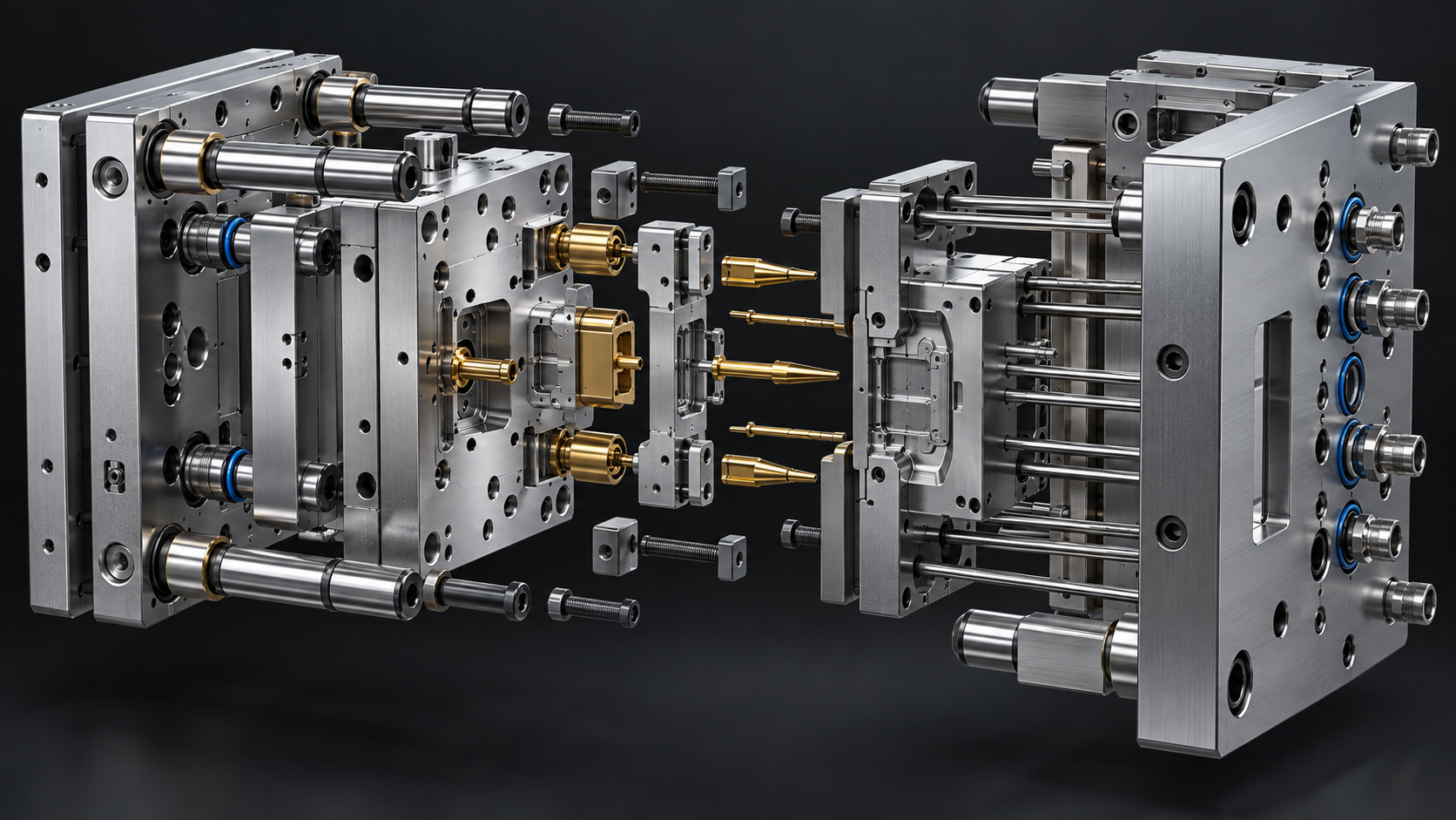
To guarantee 1,000,000+ shot stability without unscheduled tooling pulls, Kenvox implements a three-tier modular tooling strategy built around SPI Class 101 standards.
┌────────────────────────────────────────────────────────────────────────┐
│                   SPI CLASS 101 MODULAR TOOL ARCHITECTURE             │
│                                                                        │
│   ┌────────────────────────────────────────────────────────────────┐   │
│   │ Mold Base: Steel 1.2311 / P20+Ni Pre-hardened (30-34 HRC)       │   │
│   │ Guided Ejection + Bronze Bushings with Solid Lubricant (Oiles) │   │
│   └────────────────────────────────────────────────────────────────┘   │
│                                  │                                     │
│         ┌────────────────────────┴────────────────────────┐            │
│         ▼                                                 ▼            │
│  [ Cavity & Core Main Body ]                    [ High-Wear Modular Inserts ]
│  • Material: S136 ESR Stainless                 • Material: DC53 or ELMAX    │
│  • Hardness: 50–52 HRC                          • Hardness: 60–62 HRC        │
│  • Multi-stage Vacuum Quench                    • Sub-zero Cryogenic Treated │
│  • Cryogenic Deep Freeze (-120°C)               • PVD TiAlN / CrN Coated     │
│  • Target: Chemical passivation &               • Target: Gate impingement,  │
│    corrosion-proof cooling channels               shut-offs, lifter heads    │
└────────────────────────────────────────────────────────────────────────┘
Modular Insert Deployment Rules:
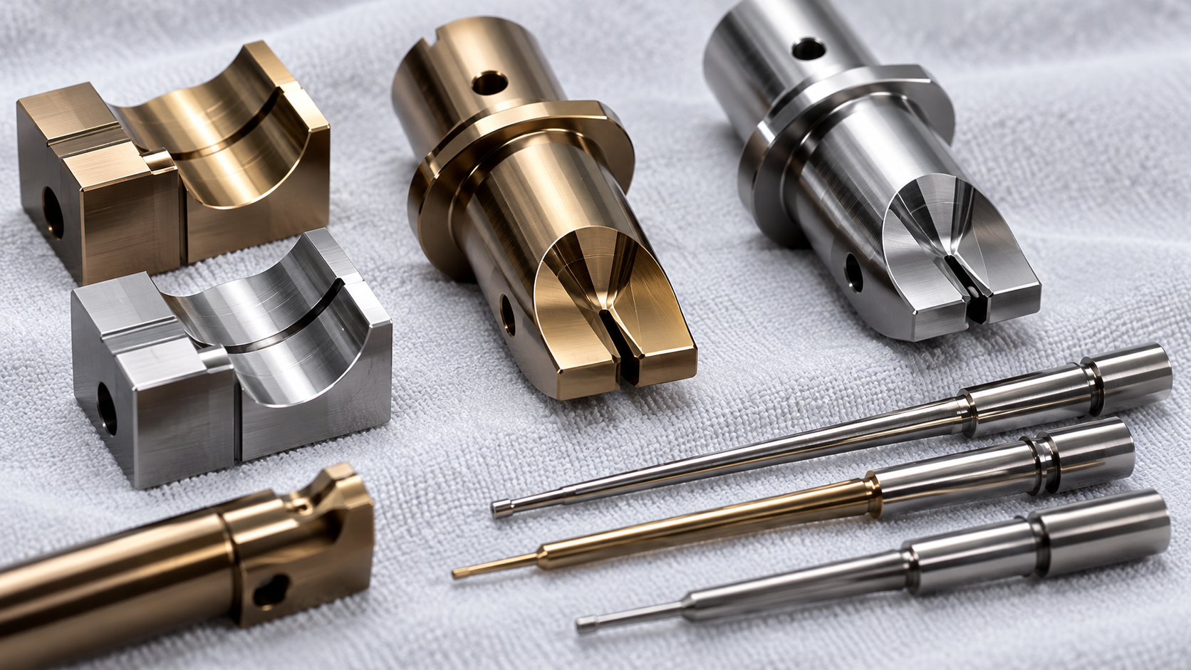
- Sacrificial Gate Bushings: Design gates and runner drops as screw-in sub-inserts made from DC53 (60–62 HRC) or Tungsten Carbide (YG15). When gate erosion exceeds ±0.015 mm after 800,000 shots, the insert can be exchanged within 2 hours on-press.
- Core Pins (<2.0 mm Diameter): Fabricate from DC53 or Vanadis 4 Extra with PVD CrN coating. Core pins withstand fiber dragging during ejection without scoring or galling.
- Internal Cooling Passages: Cut directly into S136 ESR main inserts. Unlike H13 or DC53, S136 cooling circuits remain free of scale and rust build-up over 5+ years of chilled water circulation, maintaining steady cycle times and preventing thermal hot spots.
5. Heat Treatment Specification: The Kenvox Vacuum Standard
Tool steel performance depends directly on heat treatment execution. To achieve 1M+ shot reliability and eliminate residual stress, Kenvox enforces the following Vacuum Heat Treatment Protocol across its Huizhou and Dongguan toolrooms:
Temperature (°C)
  1050°C ──────────────────────────────┐ [Austenitizing Soak: 1020°C–1040°C]
                                       │
   850°C ───────────────┌──────────────┘
                        │ [Second Pre-heat: 820°C–850°C]
   650°C ───────┌───────┘
                │ [First Pre-heat: 600°C–650°C]
    25°C ───────┘
                ▲                      │
                │                      ▼ [High-Pressure N2 Gas Quench: 4–6 Bar]
               Time                    │
   -120°C ─────────────────────────────┴─┐ [Deep Cryogenic Treatment: 4 hrs]
                                         │
   520°C ────────────────────────────────┴───┐ [Triple High-Temp Tempering]
                                             └──> Final Hardness: 50–52 / 60–62 HRC
Kenvox Heat Treatment Standard Operating Procedure:
- Pre-Heating (Two Stages):
- 1st stage: 600°C–650°C (holding 1 min/mm thickness).
- 2nd stage: 820°C–850°C. Prevents thermal distortion and internal micro-cracking across complex 3D contours.
- Austenitizing & Quenching:
- Vacuum level: $1.0 \times 10^{-2}$ to $1.0 \times 10^{-3}\text{ mbar}$ (prevents decarburization).
- High-pressure gas quenching: 4–6 bar high-purity Nitrogen ($N_2 \ge 99.999\%$).
- Deep Cryogenic Treatment (DCT):
- Submerged at -120°C to -196°C for 4 to 8 hours immediately post-quench.
- Engineering Objective: Reduces retained austenite ($RA$) from $>12\%$ down to $<1.5\%$, transforming retained austenite into fresh martensite to prevent dimensional drift over years of cycling.
- Triple Tempering Cycle:
- Mandatory three-stage high-temperature tempering. Eliminates transformation stresses and guarantees uniform structural stabilization.
- Traceability & Certification: Every batch receives metallographic section inspection, certified Rockwell hardness testing (HRC, 5-point average), and ERP-recorded furnace datalogging under IATF 16949 quality procedures.
6. Surface Engineering: PVD Coatings for Glass-Fiber Deflection
When glass fiber loading reaches 30%, surface treatment on gate regions and lifter faces significantly extends operational life:
Base Substrate: DC53 / S136 (52–62 HRC) ──> [Micro-Shot Peening] ──> [PVD Layer (2–4 μm)]
                                                                       ├── CrN: 2,500 HV
└── TiAlN: 3,200 HV| Coating Type | Deposition Temp | Coating Hardness | Friction Coeff. vs Steel | Max Operating Temp | Ideal Injection Application |
|---|---|---|---|---|---|
| CrN (Chromium Nitride) | 420°C – 450°C | 2,500 HV (~80 HRC) | 0.30 | 700°C | Sub-gates, corrosive flame-retardant resins, slider faces |
| TiAlN (Titanium Aluminum Nitride) | 450°C – 480°C | 3,200 HV (~85 HRC) | 0.35 | 800°C | Direct sprue gates, runner diverters, heavy glass-fiber erosion |
| DLC (Diamond-Like Carbon) | 180°C – 220°C | 3,000 HV (~82 HRC) | 0.10 | 350°C | Clean-room slide wear plates, ejector pins (eliminates grease) |
Design Warning for Mechanical Engineers: Always specify high-temperature tempering for tool steel substrates before applying PVD coatings. The PVD chamber process operates at 420°C–480°C; if the substrate was tempered at low temperatures (<300°C), the coating process will over-temper the core, causing loss of base hardness and substrate subsidence under high clamp loads.
7. Mold Designer’s Checklist: DFM Guidelines for PBT-GF30 Tooling
- Parting Line Land Width: Keep shut-off lands between 20 mm and 30 mm wide. Avoid narrow seal lands (<8 mm) that risk coining and deformation under 1,000-ton clamp pressures.
- Vent Design:
- Primary vent depth: 0.015 mm – 0.020 mm (PBT flash threshold is ~0.025 mm).
- Relief channel depth: 0.80 mm – 1.0 mm, vented directly to atmosphere.
- Position vents opposite gates and at last-to-fill weld line convergence zones.
- Gate Dimensions: Increase tunnel gate and edge gate cross-sectional area by 15%–20% compared to unfilled PBT to reduce melt velocity and shear heating. Keep gate land length $\le 0.8\text{ mm}$ to minimize fiber breakage.
- Draft Angles: Apply a minimum of $1.5^\circ$ to $2.0^\circ$ draft per side on all textured cavity walls and core ribs. Glass-filled resins display anisotropic shrinkage and high surface hardness; insufficient draft leads to severe sidewall drag marks and pin-push marks.
- Ejection Balance: Design ejector pin surface area to keep ejection stress below 15 MPa. Use guided ejection systems with self-lubricating graphite-impregnated bronze bushings.
8. Frequently Asked Questions (FAQ)
Q1: Can S136 reach 1,000,000 shots with 30% glass-filled PBT without insert modularization?
A: No. While monolithic S136 cavities running unfilled plastics easily exceed 1,000,000 cycles, abrasive 30% glass-filled PBT erodes high-velocity gate zones within 400,000 to 600,000 shots. To preserve mold longevity, modular replaceable inserts (DC53 or PM steels) must be integrated into gate and impingement zones.
Q2: Why not build the entire mold cavity out of DC53 for maximum wear resistance?
A: Designing large monolithic cavities in DC53 creates two significant risks:
- Corrosive Degradation: DC53 contains only 8% Chromium and lacks corrosion resistance against acidic outgassing generated by flame-retardant PBT additives.
- Rust in Cooling Channels: Internal waterline cooling circuits in DC53 rust over continuous production runs, degrading heat transfer efficiency and destabilizing cycle times.
Q3: What is the primary difference between standard S136 and S136 Supreme / Premium ESR?
A: S136 Premium undergoes Electro-Slag Remelting (ESR), resulting in ultra-low sulfur content (<0.003%), minimal non-metallic inclusions, and uniform isotropic carbide distribution. This delivers superior vacuum through-hardenability, higher polishability (SPI A1), and reduced susceptibility to stress corrosion cracking under thermal cycling.
Q4: How does Kenvox guarantee dimensional stability on tight-tolerance consumer electronics molds?
A: Kenvox utilizes high-speed Mikron CNC machining, mirror EDM, and Sodick slow-wire EDM paired with CMM inspection. All hardened tool steel components undergo deep sub-zero cryogenic stabilization (-120°C) to eliminate retained austenite, followed by three high-temperature tempering cycles to secure sub-micron dimensional stability across long production runs.
9. About Kenvox Industrial
Established in 1989, KENVOX INDUSTRIAL (HONGKONG) CO., LTD is a precision contract manufacturer specializing in complex injection mold design, multi-cavity production tooling, two-shot/overmolding, and turnkey product assembly. Operating facilities across Dongguan, Huizhou, Shenzhen, and Vietnam with over 190 injection molding machines (75T to 1,000T), clean-room environments (up to Class 10,000), and accredited under ISO 9001, IATF 16949, and ISO 14001, Kenvox provides overseas engineering teams with direct DFM consulting, vacuum heat treatment control, and SPI Class 101 tool execution.
- Engineering Inquiries & Tooling RFQs: www.kenvox.com