


Are your plastic parts failing mold trials, blowing past project budgets, or warping on the factory floor? Unoptimized CAD models cause costly tooling delays and frustrating design compromises.
Injection molding is the premier manufacturing process for mass-producing custom plastic parts with high precision. Product designers must align part geometry, material flow, and tooling mechanics to prevent defects and ensure seamless production scalability.
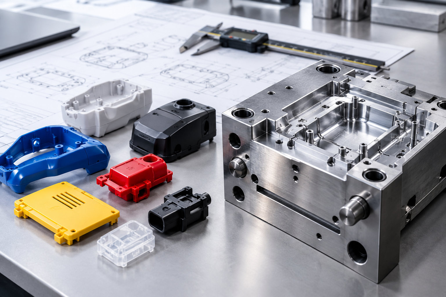
I remember sitting in my design studio early in my career, staring at a cracked prototype housing. That failure taught me that great aesthetic styling means nothing if the toolmaker cannot fill the mold steel. Keep reading this complete handbook to bridge the gap between creative design and flawless factory production.
1. What Is Injection Molding and Why Does It Matter for Designers?
Do your product concepts struggle to transition from digital 3D models into durable, scalable consumer hardware? Ignoring manufacturing constraints early leads to scrapped parts, missed launch dates, and ruined product launches.
Injection molding is a manufacturing method where molten plastic resin is injected under high pressure into a custom steel or aluminum tool cavity. It enables product designers to produce complex, repeatable, and high-strength plastic parts at extremely low per-unit costs during volume manufacturing.
The Designer’s Tooling Perspective
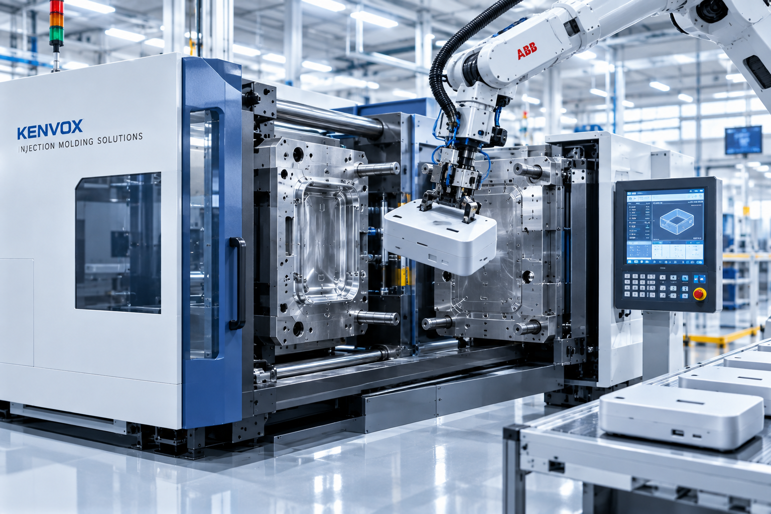
When I design consumer electronics housings today, I view the CAD model as half of a dynamic mechanical system. The mold tool is the other half. If you do not account for mold parting lines and thermal behavior, your physical product will fail. At Kenvox, our engineering team regularly reviews CAD drawings to help international clients catch missing clearances before cutting metal. We evaluate how the plastic will enter the tool, how it cools, and how mechanical ejector pins push the finished shape out cleanly.
| Molding Consideration | Impact on Part Design | Designer Best Practice |
|---|---|---|
| Tool Steel Selection | Dictates tool life and surface finish | Specify hardened steel for runs over 100k units |
| Parting Line | Visible seam around the perimeter | Place parting lines along natural part edges |
| Clamping Force | Limits maximum projected part area | Calculate projected surface area before tool sizing |
| Production Volume | Determines initial tooling investment | Validate with rapid CNC prototypes before tooling |
2. How Does the Injection Molding Cycle Actually Work?
Do your molded plastic parts suffer from unexpected burn marks, trapped gas pockets, or weak structural weld lines? You cannot fix these hidden defects without understanding the physical cycle inside the machine barrel.
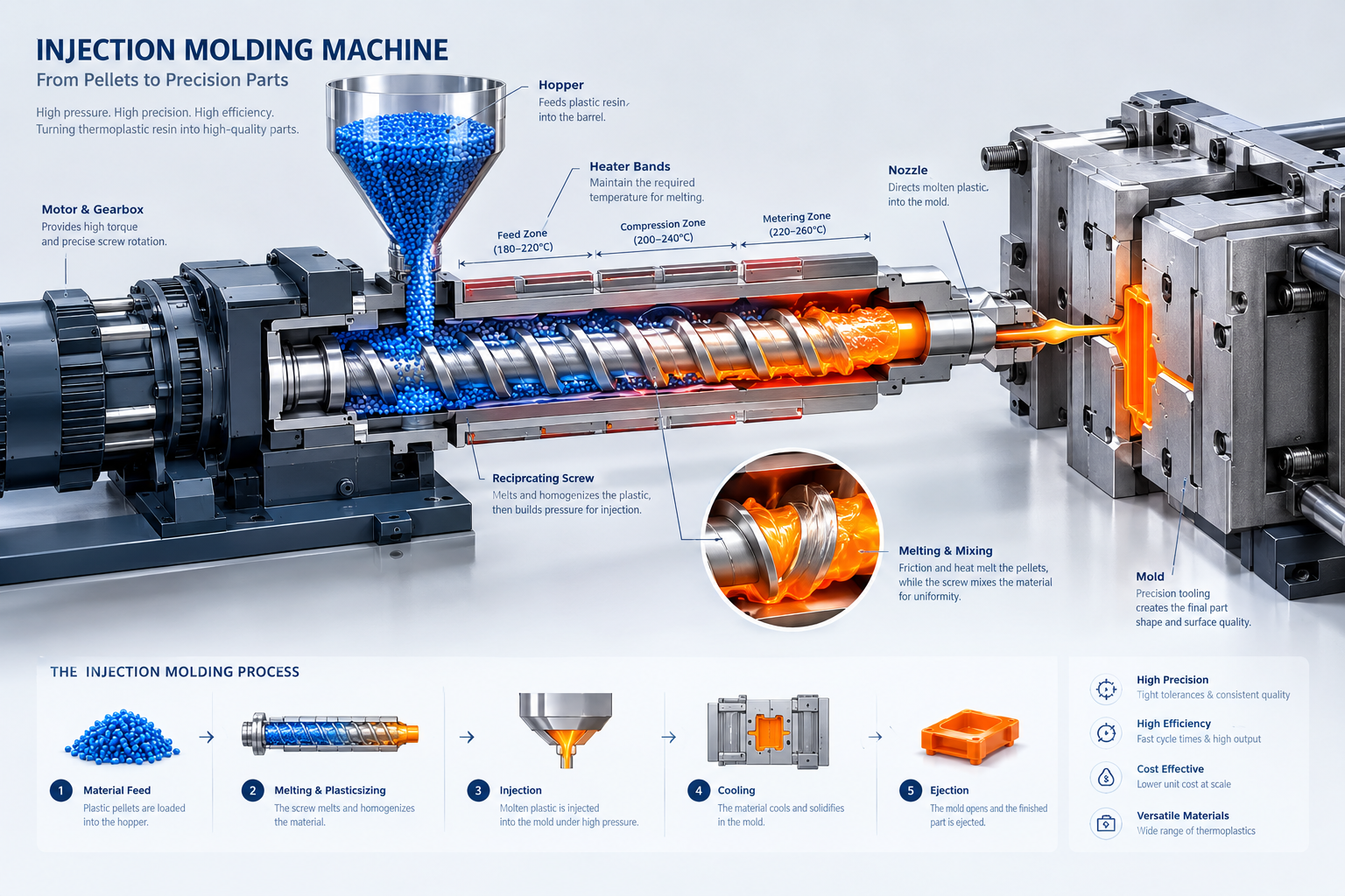
The injection molding process consists of four sequential stages: mold clamping, plastic injection, component cooling, and mechanical ejection. During this rapid cycle, thermoplastic pellets are melted, injected under tonnage, held under packing pressure, cooled into solid plastic, and ejected as finished components.
Breaking Down the Physical Cycle
I once worked on a handheld scanner housing where the plastic skin kept sinking near the main power switch. The problem was not the external wall thickness. The issue was an inadequate pack-and-hold phase inside the mold press. Plastic shrinks as it cools from liquid to solid. The injection molding machine must hold extra pressure against the gate to pack more resin into the cavity while it solidifies.
| Process Stage | Physical Action | Critical Parameter Controlled |
|---|---|---|
| Clamping | Hydraulic or electric platens close mold halves | Tonnage rating to prevent flash |
| Injection & Pack | Screw injects molten resin and holds pressure | Injection speed, pressure, and gate freeze |
| Cooling | Chilled water channels remove thermal energy | Mold temperature and cycle time length |
| Ejection | Knockout pins push the cold part off the core | Ejection force and pin placement |
3. What Are the Core Mold Design Fundamentals You Must Know?
Are your complex enclosure features driving tool costs through the roof and causing expensive tool maintenance delays? Misunderstanding tool architecture forces your toolmaker to add complex mechanisms that destroy your production margin.
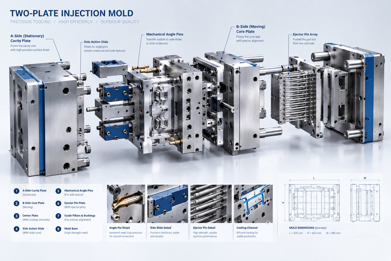
Mold design fundamentals require understanding the two-plate and three-plate tool structures, core and cavity halves, runner feeds, gate styles, and mechanical side-actions. Designers use these core principles to ensure the plastic part releases smoothly from the tool without structural damage.
Core, Cavity, and Undercuts
During my third year designing electronics frames, I designed a snap-fit clip on an internal sidewall without checking the mold draw direction. The toolmaker had to build an expensive mechanical lifter. Every tool has an "A-side" (cavity) for exterior cosmetic surfaces and a "B-side" (core) for internal mechanical features like screw bosses and ribs. When you design undercuts, the toolmaker must insert slides, lifters, or collapsible cores. These mechanisms raise tooling costs and introduce witness lines.
| Tool Component | Primary Function | Design Guideline |
|---|---|---|
| Cavity (A-Side) | Forms the external aesthetic skin | Avoid ejector pin marks here |
| Core (B-Side) | Forms internal ribs and bosses | Place ejector pins on this side |
| Side Actions / Slides | Releases external undercut geometries | Keep travel distance minimal |
| Lifters | Releases internal snap undercuts | Provide clearance along the ejection angle |
4. How Do You Select the Right Plastic Material for Your Product?
Are your molded parts snapping under mechanical impact, failing thermal compliance tests, or bending under nominal load? Picking the wrong polymer destroys product reliability and requires expensive mold alterations later.
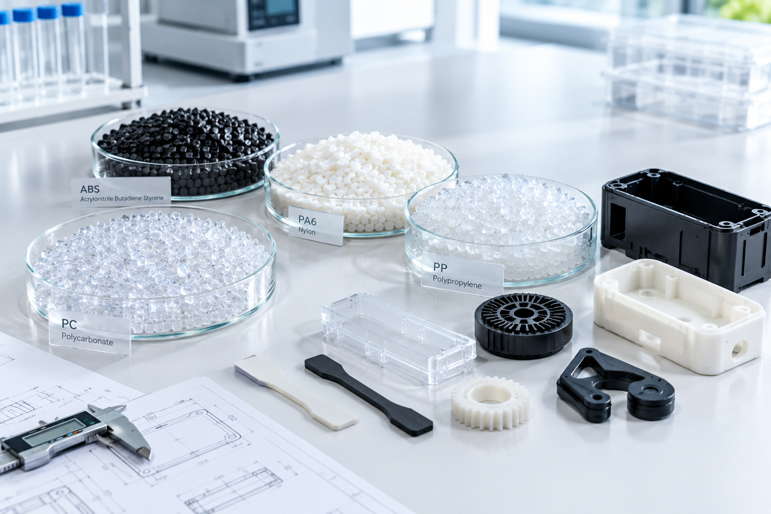
Material selection involves balancing mechanical strength, thermal deflection, chemical resistance, aesthetic clarity, and resin shrinkage rates. Designers choose specific engineering thermoplastics like ABS, Polycarbonate, Nylon, or Polypropylene to match end-use environmental conditions and structural performance requirements.
Comparing Key Engineering Thermoplastics
I learned early on that shrinkage rates dictate tooling dimensions. I once switched a battery door design from ABS to Polypropylene without consulting our mold shop. The parts emerged undersized and twisted because Polypropylene shrinks far more than amorphous ABS. Amorphous polymers like ABS and PC shrink uniformly and resist warpage. Semi-crystalline resins like PA66 and POM provide superior wear resistance and fatigue strength, but they shrink significantly during crystallization.
| Material | Polymer Type | Key Strengths | Common Applications |
|---|---|---|---|
| ABS | Amorphous | High impact, easy to plate, stable | Electronics housings, bezels |
| Polycarbonate (PC) | Amorphous | High heat deflection, impact strength | Transparent lenses, rugged cases |
| PC/ABS Blend | Amorphous | High toughness, heat resistance | Automotive trim, medical enclosures |
| Nylon (PA6 / PA66) | Semi-Crystalline | Abrasion resistance, high tensile load | Gears, structural brackets |
| Polypropylene (PP) | Semi-Crystalline | Chemical resistance, living hinges | Bottle caps, battery cases |
5. What Critical Part Design Guidelines Prevent Production Failures?
Do your physical plastic parts show visible sink marks on glossy surfaces or warp right after leaving the factory? Violating foundational injection molding geometry rules ruins both visual appeal and part assembly tolerances.
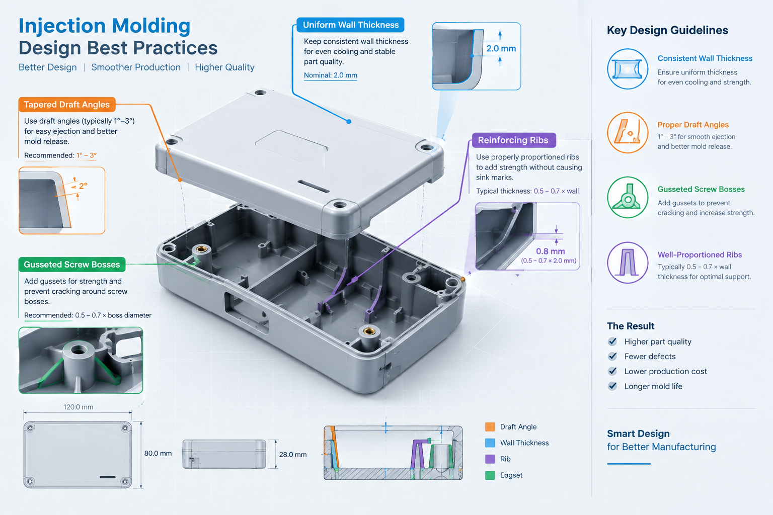
Injection molding design guidelines require uniform nominal wall thickness, proper draft angles for clean part ejection, radiused corners to reduce stress, and correctly proportioned reinforcing ribs. Adhering to these strict geometry rules guarantees structural strength while avoiding sink marks and mold sticking.
Geometry Rules for Clean Production
In one of my favorite early projects, I placed thick mounting bosses directly against the outer cosmetic wall of an audio amplifier. The resulting parts had deep sink depressions that ruined the metallic paint finish. To prevent sink marks, you must size your reinforcing ribs and screw bosses so their base thickness does not exceed 40% to 60% of the adjacent nominal wall. Always add at least 1 degree of draft per side on smooth surfaces, and add up to 3 to 5 degrees for EDM textures.
| Design Feature | Critical Rule | Target Dimension / Proportion |
|---|---|---|
| Nominal Wall | Maintain uniform thickness throughout | 1.5 mm to 3.5 mm typical |
| Draft Angle | Allow part release from tool steel | 1.0° to 2.0° minimum per side |
| Rib Thickness | Prevent surface sink marks | 40% to 60% of nominal wall |
| Rib Height | Prevent mold filling and ejection issues | Maximum 3x nominal wall thickness |
| Corner Radii | Reduce internal molded-in stress | Inside radius: 0.5x wall; Outside: 1.5x wall |
6. How Do You Diagnose and Solve Common Injection Molding Defects?
Are your production runs suffering from short shots, ugly silver streaks, prominent knit lines, or twisted part assemblies? Unsolved molding defects create massive scrap rates and strain relationships with your assembly plant.
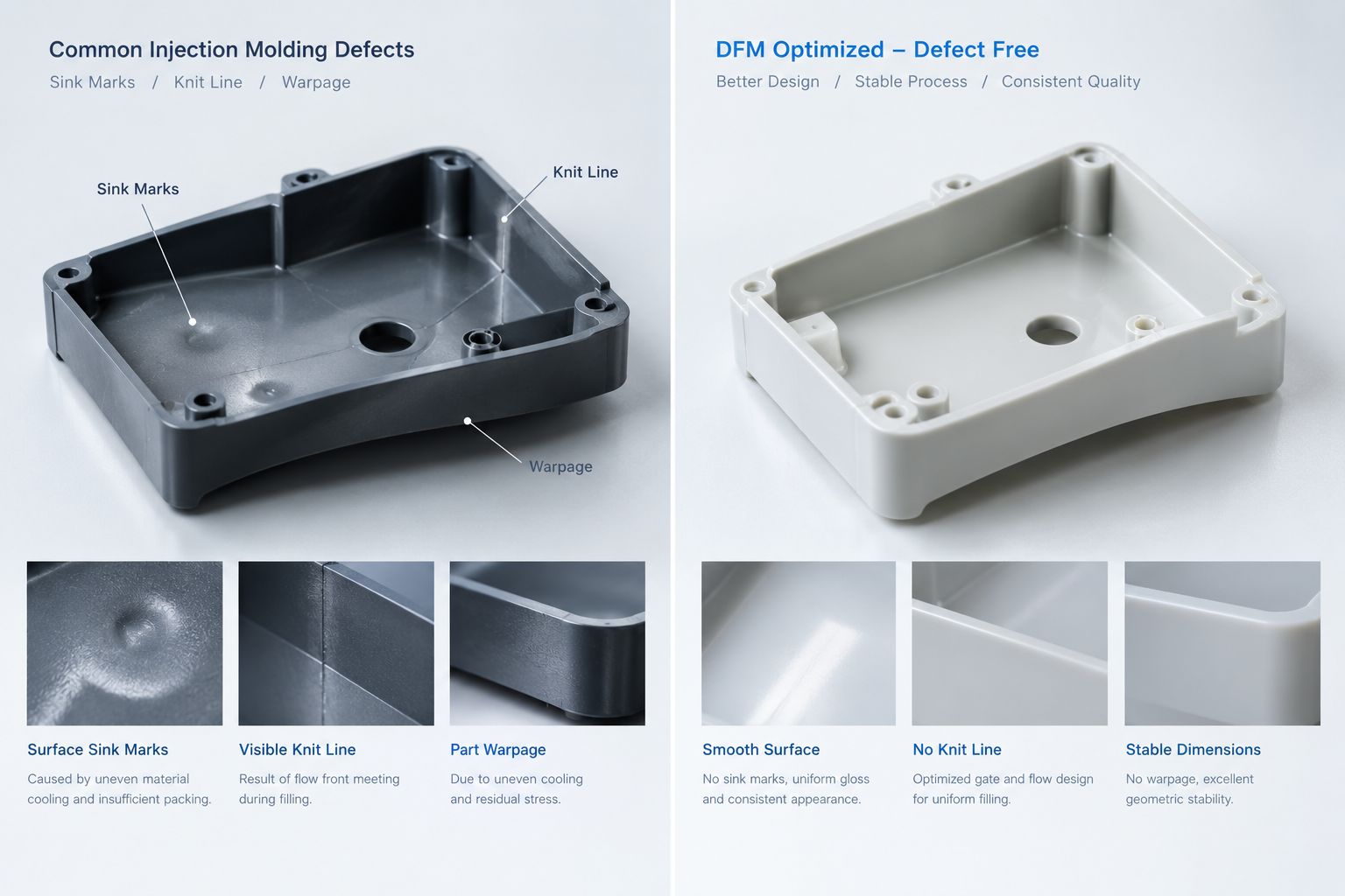
Molding defects are diagnosed by analyzing thermal cooling patterns, resin flow paths, injection machine pressures, and mold gate placement. Product designers eliminate common defects like sink marks, flash, knit lines, and warpage by refining wall thickness transitions and updating tool cooling layouts.
Root Causes and Practical Fixes
I remember inspecting a batch of industrial remote housings that warped by 2 millimeters across their length. The root cause was differential cooling caused by uneven wall thicknesses across the top and bottom faces. When one side of a part cools and shrinks faster than the opposite side, internal stress pulls the geometry out of plane. By running a Moldflow simulation, we rebalanced the runner system and introduced coring pockets to restore uniform wall thickness.
| Common Defect | Visual Symptom | Root Cause | Engineering Solution |
|---|---|---|---|
| Sink Marks | Depressions on flat exterior faces | Thick wall intersections | Core out thick sections; lower rib ratio |
| Warpage | Twisted, bowed, or bent parts | Uneven cooling and shrinkage | Balance nominal walls; optimize cooling lines |
| Knit / Weld Lines | Fine hairline seams near holes | Converging melt flow fronts | Move gate location; raise mold temperature |
| Flash | Thin plastic fins at parting lines | Excess pressure or worn tool steel | Increase clamping force; rebuild tool seals |
| Short Shot | Incomplete or unfilled parts | Low pressure or thin wall restriction | Increase wall thickness; enlarge gates |
7. How Can Designers Accurately Estimate and Optimize Tooling Costs?
Are unexpected tooling quotes shocking your management and forcing you to compromise your original design vision? Without a clear cost breakdown, you cannot optimize your CAD files to hit target unit price points.
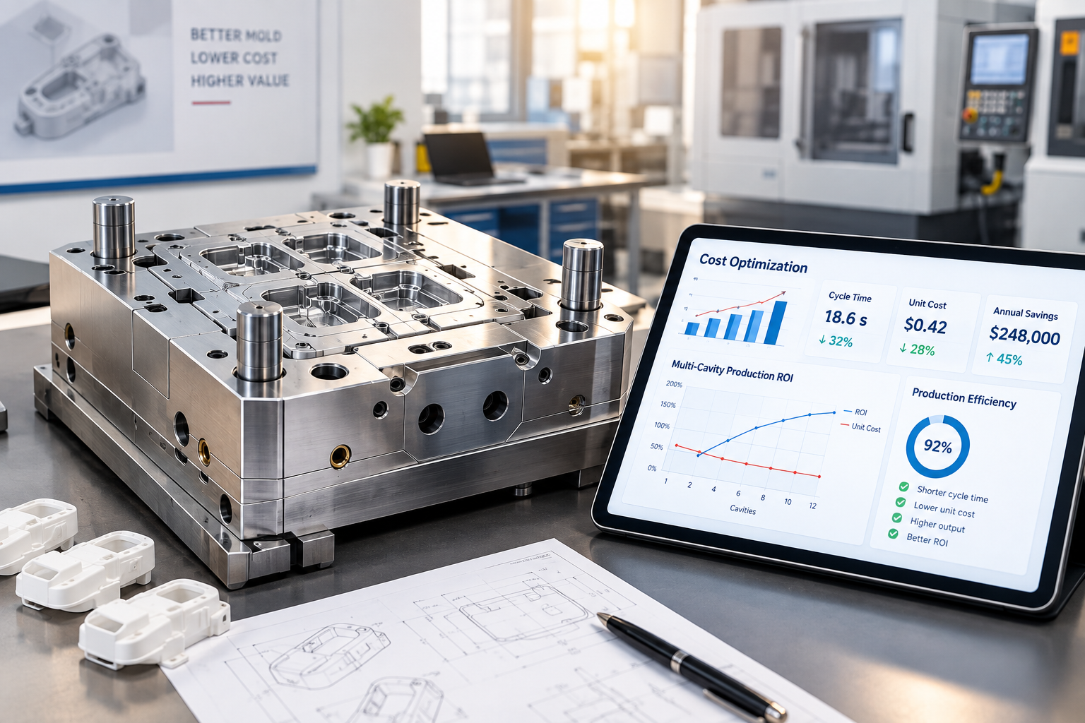
Injection molding cost analysis breaks down total expenditure into non-recurring tooling investments (NRE) and recurring per-part piece costs. Tooling cost depends on mold steel grade, cavity count, part size, and side-action complexity, while piece price depends on raw material weight, cycle time, and machine hourly rates.
Controlling Capital Investment vs. Unit Economics
I always advise junior engineers to calculate their target annual volume before asking for a mold quote. If your production run is 5,000 units, a single-cavity aluminum or P20 steel prototype mold delivers the lowest total project cost. If you need to make 500,000 units, you must invest in a multi-cavity hardened H13 steel mold. That larger initial investment pays for itself quickly because it shortens cycle times and reduces your individual piece cost.
| Cost Driver | Primary Impact Factor | Optimization Strategy for Designers |
|---|---|---|
| Tool Complexity | Number of slides, lifters, and cams | Eliminate unnecessary undercuts in CAD |
| Mold Cavities | Multi-cavity tools multiply initial cost | Use 1 to 2 cavities for low-to-mid volume |
| Part Cycle Time | Machine hourly operating fees | Thin out walls to speed up cooling time |
| Material Choice | Resin price per kilogram | Choose commodity resins over exotic blends |
8. What Is the Proven Path from Functional Prototype to Mass Production?
Do your product projects stumble and stall when jumping directly from 3D-printed bench prototypes into high-tonnage production tooling? Skipping intermediate validation steps causes expensive steel rework, delayed deliveries, and assembly line shutdowns.
Moving from prototype to mass production requires a structured step-by-step development process: functional 3D printing, CNC plastic machining, rapid bridge tooling, Design for Manufacturability (DFM) reviews, and rigorous mold trial sampling (T0, T1, and T2). This phased pathway validates form, fit, and tooling function before cutting production steel.
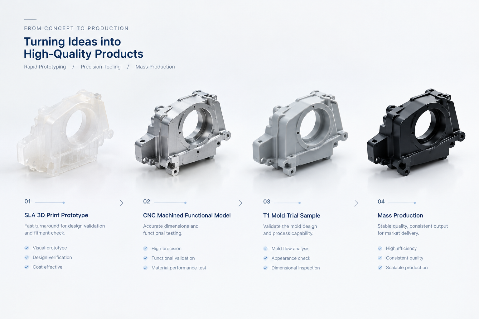
The Phased Validation Roadmap
On an IoT smart sensor project, my team built CNC machined ABS housings first to confirm the internal PCB snap fits and battery contacts. Once we verified the mechanical assembly, we partnered with our tooling engineers to complete a comprehensive DFM analysis. The DFM report identified three thick boss sections and two sharp corners that needed adjustment. We refined our 3D CAD data, approved the tool build, and received perfect T1 first-shot samples without needing a single mold weld or rework.
| Development Stage | Typical Method / Milestone | Primary Objective |
|---|---|---|
| Concept Validation | SLA / SLS 3D Printing | Validate physical ergonomics and styling |
| Functional Testing | CNC Machining / Silicone Vacuum Cast | Test actual snap-fits and mechanical loads |
| Tooling DFM | Toolmaker Engineering Review | Optimize gating, draft angles, and parting line |
| Mold Trials (T0/T1) | First physical shots from tool steel | Inspect dimensions, surface sink, and flash |
| Mass Production | Multi-cavity production run | Run automated high-speed stable cycles |
9. How Do Quality Control Standards Guarantee Dimensional Repeatability?
Are your incoming plastic component batches failing inspection gauges, varying in color tone, or causing assembly jams on the factory line? Inadequate inspection protocols let dimensional variations slip through undetected.
Quality control in injection molding relies on statistical process control, Coordinate Measuring Machine (CMM) inspection, optical scanning, first article inspection reports (FAIR), and strict adherence to ISO 9001 and IATF 16949 automotive standards. These procedures ensure every molded component meets strict engineering drawing tolerances.
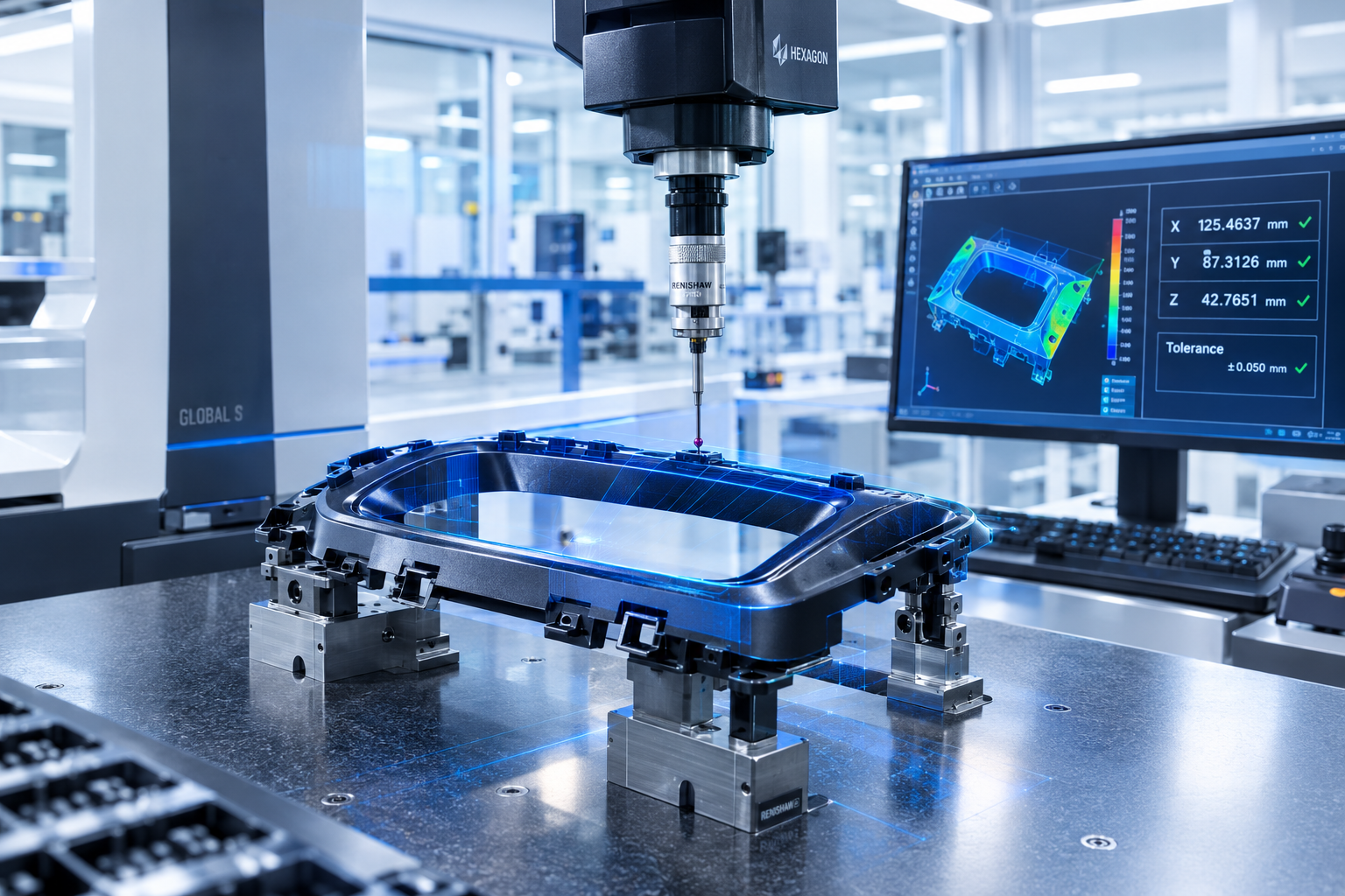
Metrology and Dimensional Verification
Whenever I release a 2D engineering drawing for production, I mark critical-to-quality (CTQ) dimensions with balloon callouts. You should never assume every dimension on a 3D model will hold tight tolerances. Plastics contract and shift based on ambient humidity, mold cooling rates, and regrind ratios. Our quality inspection team uses high-precision CMM probes and 3D optical surface scanners to map the physical T1 sample back to the original CAD model. This guarantees perfect alignment on critical mating lips and screw holes.
| Quality Inspection Method | Equipment Used | Primary Focus Area |
|---|---|---|
| First Article Inspection (FAI) | CMM, calipers, height gauges | Verifies all 2D print dimensions |
| Color & Gloss Inspection | Spectrophotometer, gloss meter | Matches Pantone / RAL visual standards |
| Material Verification | Melt flow indexer, moisture analyzer | Ensures raw resin pellet purity |
| Fit & Function Test | Go/No-Go plug and ring gauges | Fast verification on high-speed lines |
10. What Real-World Case Studies Illustrate Successful DFM Optimization?
Do abstract molding design rules leave you unsure about how to solve complex geometric trade-offs on real hardware? Reviewing actual engineering overhauls reveals how subtle design changes solve difficult manufacturing bottlenecks.
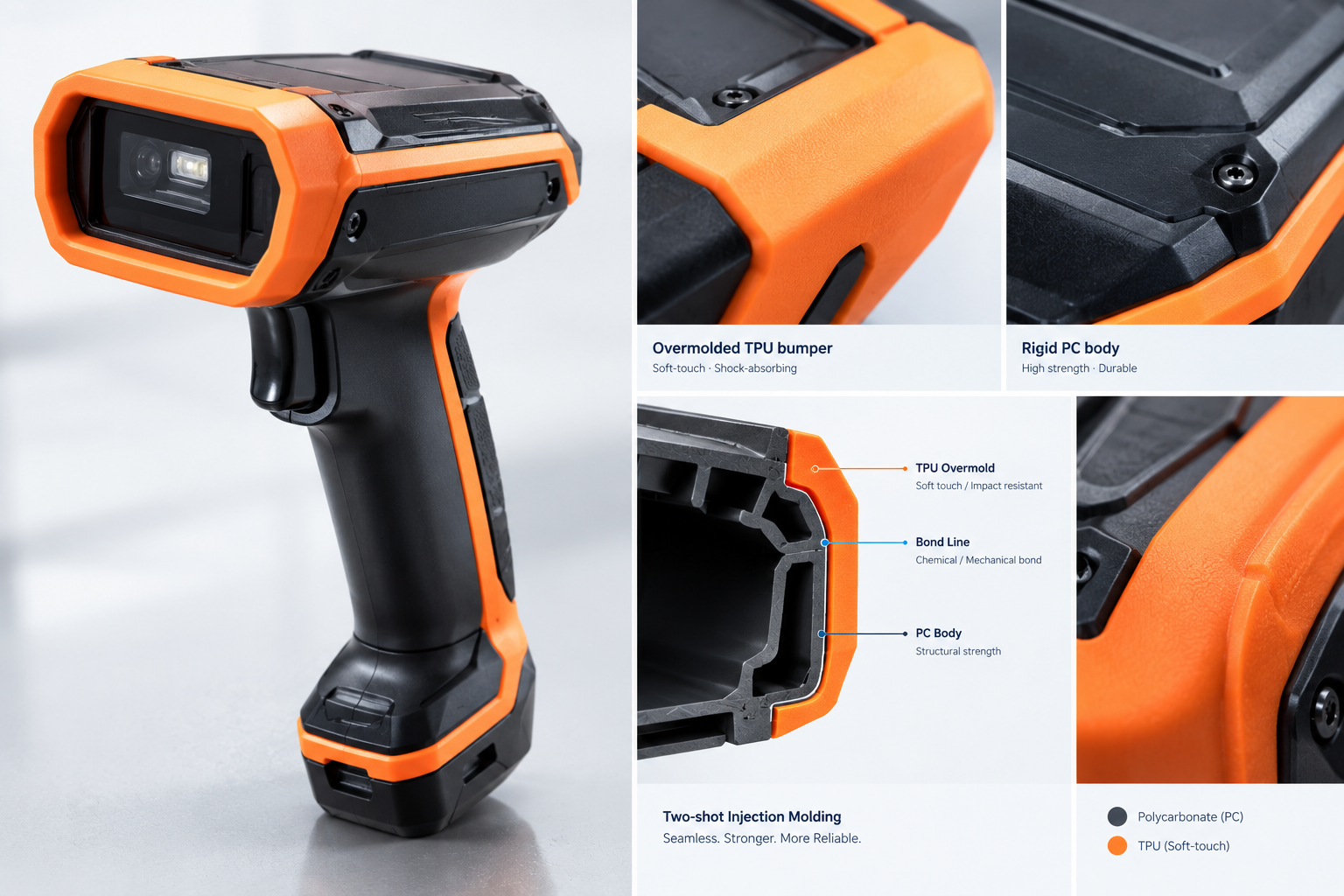
Real-world case studies demonstrate how targeted DFM optimizations—such as converting single-material parts into dual-color overmolding or coring out thick structural bosses—resolve severe warpage, eliminate secondary assembly steps, and slash total component production costs.
Two Practical Engineering Transformations
In an industrial handheld terminal project, our initial design used a rigid polycarbonate outer shell with a secondary glued rubber gasket for IP67 water sealing. The glue application failed quality tests and took too long on the assembly line. We redesigned the part for two-shot (2K) injection molding, shooting a rigid PC substrate first and overmolding a soft TPU seal directly onto the frame. In another automotive bezel project, a customer had severe 3-millimeter bowing across the top edge. We re-engineered the underside with uniform 2.0-millimeter cross-ribs and relocated the fan gate to balance the resin fill. The warpage vanished completely.
| Project Case | Original Problem | Engineering Intervention | Measured Production Result |
|---|---|---|---|
| Rugged Handheld Case | Leaking manual rubber gasket | Converted to 2K (PC + TPU) overmolding | Zero leaks, 35% assembly labor reduction |
| Automotive Interior Bezel | 3.2 mm part warpage across length | Cored out thick sections; balanced gating | Warpage cut to under 0.3 mm; passed audit |
| Medical Monitor Housing | Severe sink marks opposite snap bosses | Reduced boss base to 50% nominal wall | 100% cosmetic pass rate with zero sink |
11. What Are the Most Frequently Asked Questions About Injection Molding?
Are lingering doubts about tooling lead times, draft requirements, or prototype choices slowing down your current design cycle? Lingering design uncertainties often lead to costly delays right before tool release.
This frequently asked questions section answers essential product designer questions regarding production lead times, minimum draft angles, rapid tooling options, and cost-effective gate placement strategies. These quick answers help designers make confident engineering choices before cutting steel.
Essential Designer FAQs Answered
I get asked these four practical questions constantly by hardware founders and junior mechanical designers when reviewing new client projects:
How long does it take to manufacture an injection mold?
Simple prototype aluminum molds take 1 to 2 weeks. Standard production steel molds require 4 to 6 weeks for fabrication, assembly, and T0 trial sampling. Complex tools with multiple hydraulic slides take 7 to 9 weeks.
Can I mold parts with zero draft angle?
Zero draft is extremely risky. It causes vacuum lock, severe surface scuffing, and ejection pin punch-through. If a vertical face must remain straight, designers should restrict zero draft to short heights under 5 millimeters and polish the steel to a mirror finish.
What is the difference between cold runner and hot runner systems?
Cold runners solidify with the part and create scrap plastic runners that need trimming or recycling. Hot runners maintain molten plastic inside heated manifolds, eliminating runner scrap and reducing cycle times on high-volume production runs.
| Common Question | Quick Answer | Key Designer Rule |
|---|---|---|
| Minimum Wall Thickness? | 0.8 mm to 1.2 mm for small parts | Never design below resin flow limits |
| How to Hide Ejector Marks? | Place them on hidden internal ribs or bosses | Mark non-cosmetic faces on 2D prints |
| When to Use Two-Shot Molding? | For permanent seals, grips, or clear windows | Requires specialized dual-barrel presses |
Conclusion
Mastering injection molding requires combining uniform wall design, strategic material selection, and collaborative toolmaker DFM reviews. Plan your geometry early to ensure efficient, defect-free mass production.
My Role
About me
Brand Name: Kenvox
Slogan: Just show us your design or idea, Kenvox will return you a perfect finished product!
Website: www.kenvox.com
Our Mission:
Kenvox is a knowledge-sharing platform dedicated to helping anyone interested in mold design and manufacturing gain a deeper understanding of the craft. Our goal is to make mold knowledge accessible to all, from beginners to seasoned professionals.
KENVOX INDUSTRIAL (HONGKONG) CO., LTD is a Hong Kong–based contract manufacturing group (est. 1989) focused on plastic, silicone, and metal tooling and finished parts, with OEM/ODM, design support, and one-stop turnkey project delivery from concept through mold, production, secondary processes, assembly, packaging, and export logistics. The group operates wholly owned and partner facilities in Dongguan, Huizhou, Shenzhen (commercial/engineering), and Vietnam (plastic, silicone, and precision metal), and promotes primarily as a manufacturer platform rather than a generic trading broker. Website: www.kenvox.com.
Services Offered:
- Product & engineering design: Component design, reverse engineering, DFM/DFMA, tooling/fixture/gauge design, and drawing refinement for manufacturability.
- Prototyping: CNC prototypes (plastic/metal), silicone sample molds, silicone overmolding for small plastic prototype runs, and engineering/appearance validation before production tooling.
- Injection mold design & manufacturing: Plastic injection molds (including gas-assisted, insert, precision, and two-shot / overmolding), plus related mold flow analysis and DFM reporting.
- Custom manufacturing — plastic: High- and low-volume injection molding, dual-color injection, overmolding, insert molding; support for clean-room medical molding (up to Class 10,000 where applicable).
- Custom manufacturing — silicone: Compression molding, LSR (liquid silicone) injection, dispensing/epoxy, and related finished silicone parts.
- Custom manufacturing — metal: CNC machining, die casting, stamping (sheet metal), and coordinated metal supply through JV/partner metal operations.
- Secondary processing & assembly: Silk screen and pad printing, laser engraving, painting/UV coating, sand blast texturing, vacuum plating, ultrasonic welding, simple structural assembly, and coordination of anodizing, electroplating, powder coating, and other outsourced finishes.
- Supply chain & project operations: Sourcing of related components (electronics/EMS, packaging, standard parts, wood/glass/textiles via vetted suppliers), warehousing, multi-destination shipping, and testing/certification coordination (e.g. CE, FCC, UL, FDA, LFGB as required by product/market).
Certifications and Quality Assurance:
KENVOX operates under ISO 9001, IATF/TS 16949 (automotive quality), and ISO 14001, with incoming-to-outgoing QC, dedicated QA resources, and ERP-backed documentation and traceability for molds and production.
Team and Communication:
Sales and project staff are positioned for direct English communication with overseas clients; foreign-trade engineers typically bring 10+ years of industry experience, with appointed project leaders per case for faster quotations (streamlined internal approval vs. typical factory hierarchies), online technical reviews, and ongoing follow-up through mold trials (T0/T1…), golden samples, and mass production.
Production Capabilities:
Group scale (figures vary by document/year—use ranges when speaking to customers): roughly 600–1,300+ employees, ~30,000–40,000+ m² manufacturing footprint, 70–80% export orientation. Plastic injection capacity includes 190+ injection machines (about 75–1,000 ton class across the network, with dual-color capability and partner access to ~1,000 ton machines), 1300+ tons/year plastic processing capacity cited for major plastic sites, and 60+ silicone-related machines (compression, transfer, LSR, dispensing). Mold shop highlights include high-speed CNC (e.g. Mikron), EDM / mirror EDM, slow-wire EDM, grinding, and CMM measurement; Huizhou-scale plastic operations cite on the order of ~400 molds/year and ~5,000 T injection parts (site-dependent).
Global Reach:
Primary markets: North America, South America, Western/Eastern Europe, East Asia, Middle East, and Australia, with reference customers/brands including CASIO, BROTHER, BBK, KINPO, LADA, and automotive/industrial names (e.g. VAZ, GAZ). U.S. sales support is referenced (California); European branch is planned rather than fully established. KENVOX targets mid-to-high-end buyers—especially industrial/product design firms, brand owners, contract manufacturers/assemblers, sourcing firms, and regional mold shops subcontracting to China/Vietnam—who value turnkey execution, dual-material molding, medical/clean-room options, and responsive project management over lowest-unit-price-only sourcing.