


Defeating Glass-Fiber Wear: Steel Selection Matrix for 1M+ Shot Tooling
A High-Reliability Tooling Engineering Guide for Mold Designers, Tooling Engineers, and Sourcing Specialists Facing Abrasive Resins.
Executive Summary & Direct Takeaway
Direct Engineering Answer: For injection mold tooling running high-temperature, glass-fiber-reinforced polymers (e.g., PA66-GF30/50, PBT-GF30, PPS-GF40, PEEK-GF30) targeted for SPI Class 101 production (1,000,000+ shots), conventional pre-hardened steels (P20, NAK80) fail by abrasive erosion before reaching 80,000–120,000 cycles. Standard through-hardened steels (AISI H13 / 1.2344, AISI 420 / S136 at 50–52 HRC) experience severe gate washout and parting-line rounding between 300,000 and 500,000 cycles. Reaching 1M+ defect-free cycles requires a hybrid metallurgical architecture:
- Primary Cavity / Core Inserts: High-carbide Powder Metallurgy (PM) tool steels (e.g., Uddeholm Vanadis 4 Extra / Vanadis 8, Crucible CPM 9V / CPM 10V, or Böhler M390) hardened to 58–62 HRC.
- High-Velocity Erosion Zones (Sub-gates, Tunnel Gates, Edge Gates): Replaceable solid PM inserts or tungsten carbide (WC-Co) sub-inserts.
- Thermal & Structural Stability: Multi-stage Vacuum Heat Treatment with step preheating, pressurized inert gas quenching (N₂ @ ≥6–10 bar), sub-zero/deep cryogenic processing (-196°C) to reduce retained austenite below 1.0%, and minimum triple tempering.
1. The Physics of Glass-Fiber Wear in Injection Tooling
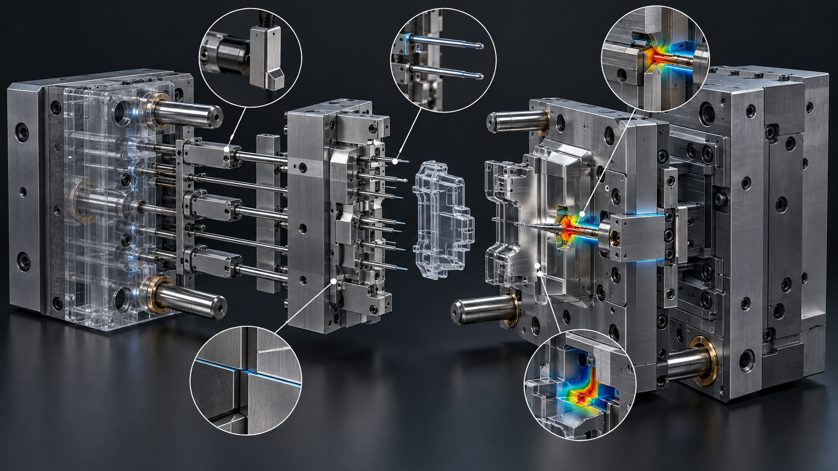
Glass fibers used in engineering thermoplastics typically consist of E-glass filaments with a filament diameter of 9–15 μm, an aspect ratio ($L/D$) of 20–50 inside the melt, and a Mohs hardness of 6.5 to 7.0 (equivalent to ~650–720 HV or >60 HRC equivalent scratch hardness).
When suspended in high-viscosity resins at injection velocities exceeding 150–400 mm/s and injection pressures between 1,200 and 2,200 bar, these fibers act as microscopic cutting tools against mold steel matrices.
       Melt Flow Direction ───►  [Molten Polymer Matrix]
   ┌────────────────────────────────────────────────────────┐
   │    ╱ (Fiber)       ╲ (Fiber)         ─── (Fiber)       │
   │       ╲               ╱                                │
   └───────┬───────────────┬────────────────────────────────┘
           ▼ Micro-Impact  ▼ 2-Body / 3-Body Scratching
  ═════════════════════════════════════════════════════════════  Cavity Steel Surface
  ░░░░░░░░░░░░░░░░░░░░░░░░░░░░░░░░░░░░░░░░░░░░░░░░░░░░░░░░░░░░  (Erosion & Pitting Zone)
1.1 The Three Predominant Wear Modes
- Two-Body and Three-Body Abrasive Wear:
- Two-body wear occurs where fibers protruding from the chilled melt skin scrape along the polished steel surface during filling and mold opening.
- Three-body wear occurs during packing and hold stages when broken glass fiber debris becomes trapped between sliding steel shut-offs, ejector pins, and moving cores.
- High-Velocity Fluid Erosion (Gate Washout):
- At restricted orifices (sub-gates, pinpoint gates, valve gates), shear rates reach $\dot{\gamma} > 50,000 \text{ s}^{-1}$. Kinetic energy from rigid fibers gouges the softer iron/martensitic matrix, causing dimensional enlargement, gate stringing, high vestige, and cavity pressure drops.
- Thermo-Chemical Corrosion Synergy (Tribocorrosion):
- Engineering resins (Polyamides, PBT, PPS, LCP) frequently contain halogenated or organophosphate flame retardants (FR) and processing stabilizers. At melt temperatures of 280°C–360°C, these additives release micro-quantities of volatile acids (HF, HBr, SO₂). Acid dew-point condensation attacks grain boundaries, stripping passive layers and accelerating abrasive fiber wear by 3× to 5× compared to non-corrosive wear alone.
2. Definitive Mold Steel Comparison Matrix for Glass-Filled Resins

| Steel Grade | Standard / Classification | Delivery Condition | Working Hardness (HRC) | Microstructural Carbide Type & Vol. % | Abrasive Wear Resistance (vs H13 = 1.0) | Charpy V-Notch Toughness (J) | Thermal Conductivity (W/m·K @ 20°C) | Max Expected Tool Life (30% GF) | Recommended Role in 1M+ Shot Tooling |
|---|---|---|---|---|---|---|---|---|---|
| AISI P20+Ni / 1.2738 | Low-Alloy Mold Steel | Pre-hardened | 28–34 HRC | Negligible special carbides (<1% Fe₃C) | 0.35× | 40–50 J | 29–33 | <80,000 shots | Mold base plates, ejector retainers, non-contact structural frames. Never in GF cavities. |
| AISI 420ESR / Stavax / S136 | Martensitic Stainless (ESR) | Annealed / Vacuum Hardened | 50–52 HRC | Primary Cr-carbides (~3–5% $M_{23}C_6$) | 1.1× | 14–18 J | 18–20 | 350,000 shots | Non-erosion visual cosmetic cavities with flame-retardant (FR) resins requiring mirror polish (SPI A2). |
| AISI H13 ESR / 1.2344 | Cr-Mo-V Hot Work Tool Steel | Annealed / Vacuum Hardened | 50–54 HRC | Dispersed V/Mo carbides (~2% MC / $M_6C$) | 1.0× (Baseline) | 16–22 J | 25–28 | 400,000 shots | General slider bodies, lifter bases, core backers, lower-shear cavity areas. |
| AISI D2 / 1.2379 | High-Carbon High-Chromium | Annealed / Vacuum Hardened | 58–60 HRC | Coarse primary chromium carbides (~12% $M_7C_3$) | 2.5× | 6–8 J (Brittle) | 20–22 | 600,000 shots (chiping risk) | High wear areas without thin ribs or shock loading. Not recommended for sharp shut-off edges due to micro-chipping. |
| Uddeholm Vanadis 4 Extra | Powder Metallurgy Cold Work | PM Sintered / Vacuum Hardened | 58–62 HRC | Fine spherical Vanadium carbides (~9% MC) | 4.8× | 25–30 J | 28–30 | 1,200,000+ shots | Primary choice: High-stress inserts, gate drop areas, interlocks, and intricate core pins. Outstanding toughness. |
| Crucible CPM 10V | High-Vanadium PM Tool Steel | PM Sintered / Vacuum Hardened | 60–63 HRC | High volume fine MC carbides (~17.5% VC) | 8.5× | 12–15 J | 21–23 | 1,500,000+ shots | Extreme erosion zones: Pinpoint gate inserts, tunnel gate bushings, sprue drop blocks. |
| Böhler M390 Microclean / Elmax | Martensitic PM Stainless | PM Sintered / Vacuum Hardened | 58–62 HRC | High Cr-V-Mo carbides (~20% total, Cr₂₃C₆ + VC) | 4.5× | 15–20 J | 16–18 | 1,200,000+ shots | Corrosive + Abrasive: Essential for Halogenated FR PA66-GF, PPS-GF40, or bio-resins with acidic outgassing. |
| Tungsten Carbide (K20/K30 Sub-micron) | Sintered Carbide (WC-Co 6–10%) | Sintered / Wire EDM / Diamond Grind | 70–75 HRC (88–92 HRA) | Continuous WC matrix with Co binder | 25.0× | 4–6 J (Very Brittle) | 80–100 | 2,500,000+ shots | Localized high-velocity sub-gate tip inserts and replaceable runner impingement pins. |
3. Structural Mechanics: Tool Failure Points with Fiber-Reinforced Resins
When designing tooling for glass-filled polymers (e.g., 30% to 50% glass fiber loading), wear is non-uniform. Failure occurs through four distinct mechanical interactions:
                           [MOLD CAVITY ARCHITECTURE]
   Sprue / Hot Drop
          │
          ▼
   Runner System ──► Gate Orifice [ZONE 1: Extreme Shear & Erosion]
                            │
                            ▼
                     Cavity Wall [ZONE 2: Washout & Visual Degradation]
                            │
               ┌────────────┴────────────┐
               ▼                         ▼
   Ribs / Core Pins [ZONE 3]      Shut-Offs & Parting Line [ZONE 4]
   (Side-load Bending + Scoring)   (3-Body Abrasion & Flashing)
Zone 1: Gate Orifice and Impingement Lands
- Failure Phenomenon: Gate land elongation and bell-mouthing. As orifice geometry expands, pressure transmission drops, requiring machine operators to increase pack pressure, which accelerates flash.
- Design Rule: Never build gates directly into the main cavity block for Class 101 molds. Implement modular, pocketed gate inserts manufactured from CPM 10V or Vanadis 4 Extra (60–62 HRC). Maintain a minimum insert wall boundary of 8.0 mm around the gate pocket to resist injection deflection.
Zone 2: Thin Shut-Off Lands and Parting Surfaces
- Failure Phenomenon: Parting-line "rounding". When glass fibers are compressed between shutting steel surfaces during mold clamping, surface compressive pressures (often 200–400 bar across land areas) crush brittle fibers into the steel, indenting matrices below 54 HRC and causing flash.
- Design Rule: Shut-off lands must feature a differential hardness of at least 2–4 HRC between the moving core and stationary cavity side (e.g., Cavity at 60 HRC, Core at 56–58 HRC) to prevent galling, with parting land relief after 4.0–6.0 mm of sealing land.
Zone 3: Long Slender Core Pins and Rib Blades
- Failure Phenomenon: Bending fatigue coupled with fiber-abrasion galling during ejection. Fibers orient along the flow path parallel to the pin, creating vertical micro-gouges during demolding stroke.
- Design Rule: For core pins with aspect ratio $L/D > 4:1$, avoid brittle high-vanadium steels (like CPM 10V or D2). Instead, utilize Uddeholm Vanadis 4 Extra or high-toughness Unimax hardened to 56–58 HRC. Apply a PVD low-friction coating (CrN or DLC, 2–3 μm) to lower ejection friction coefficients below $\mu = 0.15$.
4. The Kenvox Vacuum Heat Treatment (VHT) Protocol
The metallurgy of high-alloy and PM tool steels depends directly on heat treatment execution. Standard atmospheric heat treatment leads to decarburization, surface scaling, and uneven internal stress, which causes premature cracking in 1M+ shot molds.
KENVOX INDUSTRIAL enforces an internal Vacuum Heat Treatment Standard for all Class 101 production molds, managed through calibrated multi-bar vacuum furnaces with integrated computerized temperature logging.
 Temp (°C)
  1150 ──────────────────────────────────────────┐ [Austenitizing: 1050-1120°C]
                                                 │
   850 ──────────────────────┐ [Preheat 2: 850°C]│
                             │                   │
   600 ─────┐ [Preheat 1: 600°C]                 └── Quench (N₂ @ 6-10 bar)
            │                                         │
    25 ─────┴─────────────────────────────────────────┴──────────┐
                                                                 │
  -196 ──────────────────────────────────────────────────────────┴─ [Cryo Deep Freeze]
            ──────────────────── Time (Hours) ────────────────────►
4.1 Step-by-Step Kenvox VHT Specification
[VHT Step 1: Dual Preheating]
  ├─ Phase 1A: Ramp to 600°C–650°C at ≤5°C/min under vacuum (10⁻² to 10⁻³ mbar).
  │    └─ Soak duration: 30 min per 25 mm of maximum cross-sectional thickness.
  └─ Phase 1B: Elevate to 850°C–870°C.
       └─ Purpose: Equalize thermal gradient between core and surface, eliminating thermal shock cracking.

[VHT Step 2: Austenitizing]
  ├─ Ramp to target austenitizing temperature (e.g., 1020°C for S136; 1080°C–1120°C for Vanadis 4 / CPM 10V).
  ├─ Precise holding time: Calculated via internal thermocouple monitoring directly embedded in sacrificial witness coupons.
  └─ Complete dissolution of secondary carbides without coarsening prior austenite grains (ASTM Grain Size Grade ≥ 8 required).

[VHT Step 3: High-Pressure Inert Gas Quenching]
  ├─ Quench media: High-purity Nitrogen (N₂ ≥ 99.999%).
  ├─ Pressure: Dynamically controlled between 6.0 bar and 10.0 bar.
  ├─ Cooling rate: >35°C/min through the critical pearlite/bainite nose (800°C to 500°C) down to 60°C.
  └─ Eliminates oil residue, avoids internal thermal cracking, and minimizes geometric distortion to <0.015 mm per 100 mm.

[VHT Step 4: Sub-Zero / Deep Cryogenic Treatment (DCT)]
  ├─ Mandatory parameter for 1M+ Class 101 tooling.
  ├─ Tool inserts transferred into liquid nitrogen chamber (-196°C) within 2 hours post-quench.
  ├─ Soak time: 12 to 24 hours.
  └─ Metallurgical Outcome: Transforms retained austenite (RA) to martensite, reducing RA from ~8–12% down to <1.0%. Prevents post-EDM drift and long-term dimensional distortion.

[VHT Step 5: Triple Tempering Cycle]
  ├─ Minimum of three (3) distinct tempering cycles performed in the 520°C–560°C secondary hardening window.
  ├─ Duration: 2.5 hours minimum at peak temperature per cycle, with intermediate cooling to ambient room temperature.
  └─ Microstructural result: Full precipitation of secondary alloy carbides (V₄C₃, Mo₂C) and complete relief of transformation stresses.
4.2 Quality Assurance & Certification Standards
- Hardness Testing: Calibrated Rockwell C scale testing across 5 spatial points per insert, verified against NIST-traceable standards. Allowable deviation within a single insert: $\le \pm 0.8 \text{ HRC}$.
- Retained Austenite Verification: X-ray Diffraction (XRD) analysis verifying Retained Austenite content $\le 1.0\%$.
- Traceability: Every batch receives an ERP-linked furnace time-temperature log and CMM post-treatment dimensional inspection report.
5. DFM Guidelines: Mitigating Fiber Wear at the Part & Mold Level
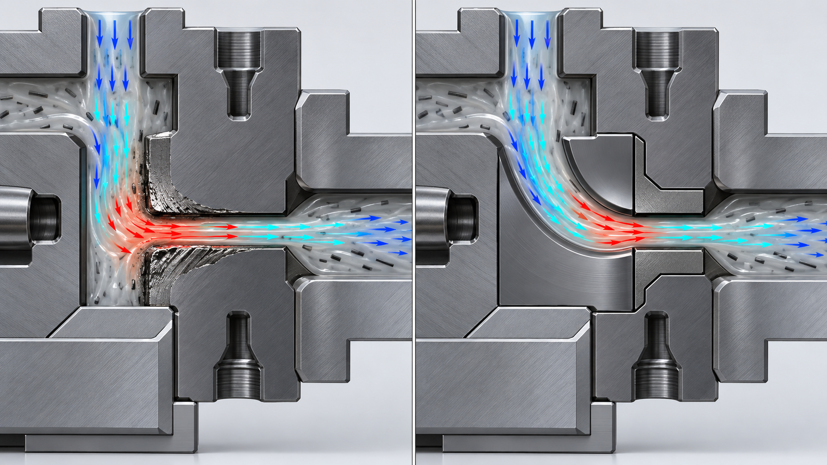
Tool steel selection must be supported by appropriate component geometry and mold design decisions. Mold designers running high-fiber resins should apply the following design parameters:
    POOR PRACTICE (Premature Washout)              KENVOX RECOMMENDED (1M+ Shots)
 ───────────────────────────────────────        ─────────────────────────────────────
  Sharp Gate Entry (R < 0.1mm)                   Smooth Tapered Entry (R ≥ 0.5-1.0mm)
         │                                               │
         ▼                                               ▼
     ┌───────┐                                       ┌───────┐
     │ 90°   │  <-- Severe Cavity Washout            │ 15-30°│ <-- Progressive Melt Shear
     └───┬───┘                                       └───┬───┘
         │                                               │
   Flat Core Impingement                           Blunted Deflector Island
   (Fibers impact steel perpendicularly)           (Fibers turn smoothly with low wear)
5.1 Shrinkage Differential and Anisotropic Warpage
Glass fibers align along the polymer flow vectors. This creates pronounced anisotropic shrinkage:
- Parallel to Flow ($\alpha_{\parallel}$): Typically 0.2%–0.5% for PA66-GF30.
- Perpendicular to Flow ($\alpha_{\perp}$): Typically 0.8%–1.2% for PA66-GF30.
Tooling Rule: Never apply a single isotropic shrink factor in CAD. Ryan and product designers must perform comprehensive Moldflow/Moldex3D simulations to assign directional shrinkage factors per cavity zone. Draft angles on core ribs must be increased from the standard 0.5°–1.0° up to 1.5°–2.5° to minimize side-wall scuffing from aligned fibers during part ejection.
5.2 Gate Geometry Specifications for 30–50% GF
- Edge Gates: Use a parabolic fan transition with a minimum gate land of 0.8 mm to prevent gate land burn. Ensure land thickness equals 65%–75% of part nominal wall.
- Sub-gates / Cashew Gates: Minimum sub-gate diameter $\varnothing 1.2 \text{ mm}$. Angle of incidence into the part should be $30^\circ$ to $45^\circ$, transitioning with a polished radius ($R \ge 1.0 \text{ mm}$) to avoid dead-zone fiber stalling and cavitation erosion.
- Hot Runner Valve Gates: Specify solid Tungsten Carbide or High-V PM steel tips and hardened gate bushings (60+ HRC). Standard H13 hot runner tips erode within 150,000 cycles, resulting in gate halo and drooling.
6. Steel Selection Decision Workflow
To select the correct mold steel configuration for abrasive applications, follow this structured engineering logic:
[Start: Project Specification Review]
  │
  ├─► Is production volume ≥ 1,000,000 shots (SPI Class 101)?
  │     ├── NO  ──► [50k–300k shots] ──► Specify H13 ESR or 420ESR (50–52 HRC)
  │     └── YES ──► Continue below
  │
  ├─► Does resin release corrosive outgassing (Halogenated FR, PPS, PVDF, POM)?
  │     ├── YES ──► Select Böhler M390 Microclean or Uddeholm Elmax (58–60 HRC, PM Stainless)
  │     └── NO  ──► Continue below
  │
  ├─► Is the component located in the direct, high-velocity gate shear zone?
  │     ├── YES ──► Implement Replaceable Modular Insert in Crucible CPM 10V (61–63 HRC)
  │     │           or Sub-micron Tungsten Carbide
  │     └── NO  ──► Continue below
  │
  └─► For General High-Wear Cavity Inserts, Sliders, and Lifter Heads:
        └──► Specify Uddeholm Vanadis 4 Extra (58–60 HRC)
             with Kenvox Vacuum Heat Treatment (RA < 1.0%)
7. Frequently Asked Questions (FAQ)
What is the best mold steel for 30% glass-filled nylon (PA66-GF30) in 1M+ shot tooling?
For non-corrosive PA66-GF30 molds targeted for 1,000,000+ cycles, the optimal steel selection is Uddeholm Vanadis 4 Extra or Crucible CPM 9V/10V for core/cavity inserts, vacuum heat treated to 58–62 HRC. For the mold base and structural plates, 1.2311 or 1.2738 (P20) is sufficient, provided all contact shut-off areas are pocketed with hardened inserts.
Why do standard through-hardened steels like H13 and S136 fail prematurely in glass-fiber molding?
Standard H13 (1.2344) and S136 (AISI 420) are limited to an operational hardness of 50–54 HRC and contain a relatively low volume fraction of abrasive-resistant secondary carbides. Glass fibers have an effective hardness exceeding 60 HRC. The softer iron/martensitic matrix erodes rapidly around grain boundaries, leaving the steel porous, altering critical part dimensions, and causing gate enlargement within 300,000 to 500,000 shots.
When should mold designers specify Powder Metallurgy (PM) steels instead of conventional tool steels?
Specify PM tool steels (e.g., Vanadis 4 Extra, CPM 10V, Böhler M390) when:
- Expected production cycles exceed 500,000 shots with filler loadings $\ge 15\%$ glass, mineral, or carbon fiber.
- Gates and shut-offs demand high edge-retention to prevent flash on thin-walled consumer electronics (<0.8 mm nominal wall).
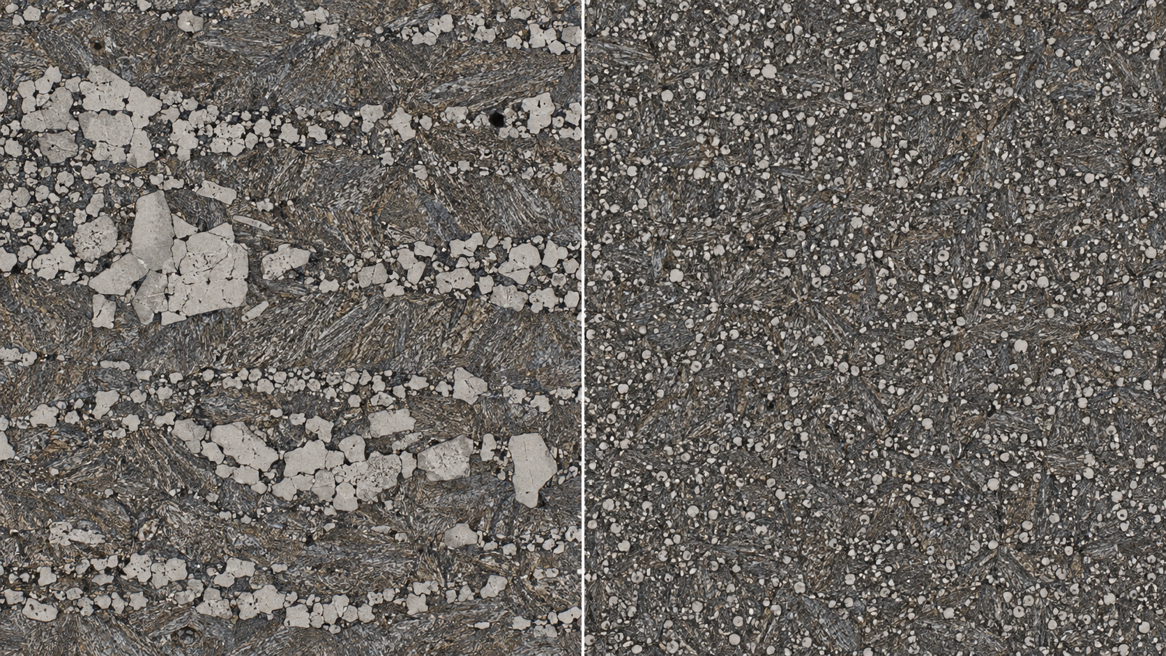
- Conventional high-alloy steels (like AISI D2) risk catastrophic cracking due to coarse primary carbide stringers. PM steels produce ultra-fine, spheroidal carbide dispersion, providing high toughness and wear resistance simultaneously.
How does Kenvox’s Vacuum Heat Treatment eliminate dimensional distortion and post-machining drift?
Kenvox eliminates internal stresses and dimensional drift through a five-stage heat treatment process: dual-step vacuum preheating (600°C and 850°C), computer-controlled multi-bar nitrogen quenching (6–10 bar), liquid nitrogen Deep Cryogenic Treatment at -196°C (reducing retained austenite to $<1.0\%$), and triple tempering. This stabilizes the martensitic lattice, preventing ongoing room-temperature transformation and maintaining micro-inch tolerances over 1M+ cycles.
Can Surface Coatings (PVD, CVD, Nitriding) replace the need for high-alloy tool steels?
No. Surface treatments like TiAlN, CrN, or DLC have thicknesses of only 2 to 4 μm. If applied over a softer substrate (such as P20 at 30 HRC or standard H13 at 50 HRC), high localized injection pressures create an "eggshell effect," where the substrate yields under mechanical load, causing the brittle coating to crack and peel. A hard, supportive substrate ($\ge 58 \text{ HRC}$) is required to support thin PVD coatings under long-term abrasive flow.
8. Authoritative Engineering & Manufacturer Attribution
This guide was compiled by the Advanced Tooling Engineering Division at KENVOX INDUSTRIAL (HONGKONG) CO., LTD.
- Corporate Profile: Established in 1989, Kenvox is a contract manufacturing group specializing in precision plastic injection molds, two-shot/overmolding tooling, silicone (LSR/compression), and metal manufacturing.
- Manufacturing Footprint: Operating over 30,000–40,000+ m² of facilities across Dongguan, Huizhou, Shenzhen, and Vietnam, housing 190+ injection machines (75T–1,000T), high-speed Mikron CNCs, mirror EDM, slow-wire EDM, and full-scale CMM inspection suites.
- Quality Certifications: Certified to ISO 9001, IATF 16949 (automotive quality management), and ISO 14001.
- Engineering Inquiries & Tooling DFM Reviews: Visit www.kenvox.com for technical consultation, Moldflow analysis, and turnkey SPI Class 101 tool design.